


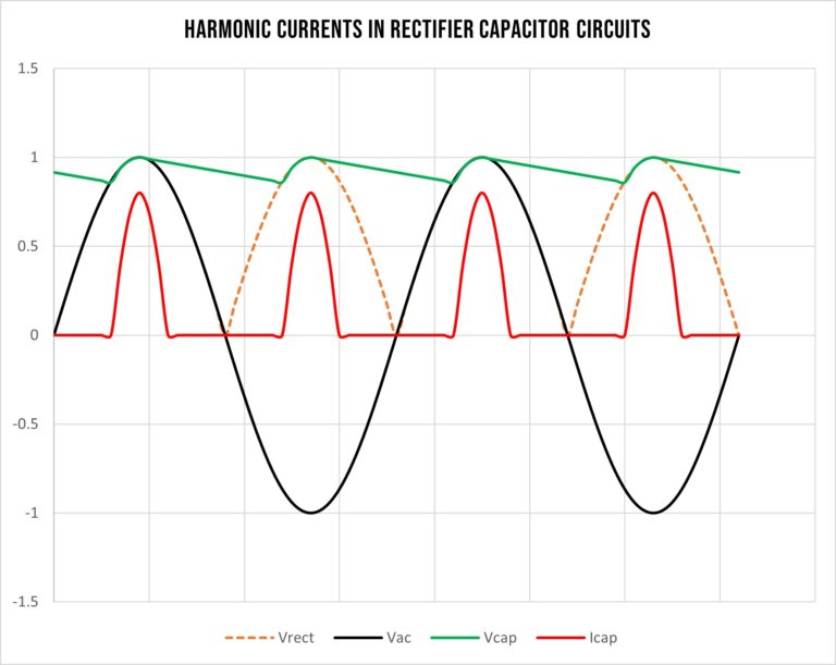
Power Factor Correction, Harmonic Currents & EN61000-3-2
21st February 2023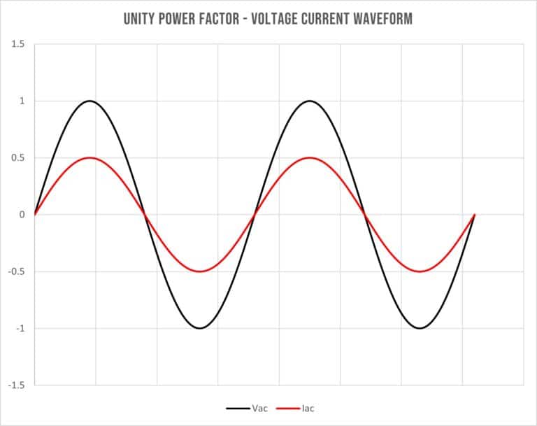
sign up for our newsletter
Enter your email address below
LET’S MAKE THIS EASY. CALL 01929 555 700
why choose relec?
-

Faster
Our aim is to get back to you with an initial response within the hour.
-
Attention to detail
We pride ourselves on getting you the right product, at the right price and on time.
-
New ideas
We are constantly looking for latest technology and products for your applications.
-
Beyond standard
It’s not just about the product. Our service goes way beyond the norm.
-
Easy
We want to make your life as simple as it can be. Call us to find out what we can offer.


